 EN

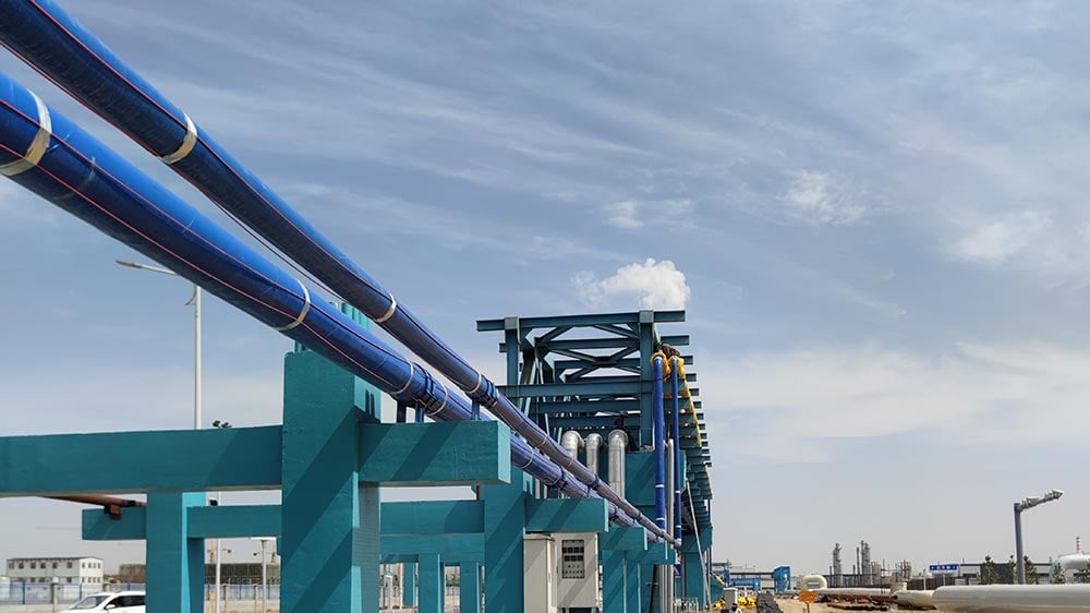
Low winter temperatures create common risks for buildings and industrial facilities, including frozen or ruptured pipes and ice accumulation on roof edges and gutters. Conventional constant wattage heating cables provide a relatively consistent rated heat output per unit length under specified operating conditions. Although a thermostat can switch the entire circuit on and off, constant wattage cable cannot automatically adjust the output of individual sections according to local temperature variations along the pipe.
Energy efficient heating systems combine appropriate heating cable selection, temperature controls, thermal insulation, and electrical components to optimize system operation. By reducing unnecessary heat output and operating time where conditions permit, a properly designed system can help lower long-term operating costs. Actual energy performance depends on project conditions, heat loss, product selection, and the control strategy; it cannot be determined from cable type alone.
1. Energy Characteristics of Conventional Heat Tracing Systems
Constant wattage heating cables are designed to provide a relatively consistent rated heat output per unit length under specified operating conditions. A thermostat or control system can switch the entire circuit on and off. However, the cable itself cannot automatically adjust the heat output of individual sections according to local temperature variations in the same way as Self Regulating Heating Cable.
When different sections of a pipeline have different ambient temperatures, wind exposure, insulation thicknesses, or heat losses, a single temperature measurement point may not fully represent the thermal conditions along the entire pipeline. If the control strategy or sensor location is inappropriate, the system may provide insufficient heating in some areas or unnecessary heat in others.
System energy consumption therefore depends not only on the type of heating cable, but also on temperature control, sensor placement, insulation design, operating time, and site conditions. A sound system design must consider both the cable characteristics and the control strategy for the complete heat tracing circuit.
2. How Self Regulating PTC Technology Helps Optimize Energy Use
The core heating element of Self Regulating Heating Cable is a conductive polymer heating core with Positive Temperature Coefficient (PTC) characteristics. The cable typically contains two parallel bus wires, with conductive polymer material positioned between them to form a distributed heating element along the cable.
At low temperatures, the conductive polymer matrix contracts. The contact conditions between conductive particles change, and the number of conductive pathways generally increases. Electrical resistance typically decreases. At a constant supply voltage, current increases and heat output rises.
As the local temperature increases, the conductive polymer matrix expands. The contact conditions and conductive pathways between particles change, increasing electrical resistance. Current decreases, and heat output is automatically reduced. When the temperature falls again, resistance generally decreases and heat output increases accordingly.
Some Self Regulating Heating Cables use manufacturing processes such as irradiation cross-linking to improve the structural stability and thermal performance of the conductive polymer material. However, material formulations and manufacturing processes vary by manufacturer and product model. A specific process should not be treated as a universal construction requirement for all self-regulating cables.
This PTC characteristic allows different sections along the cable to adjust their heat output according to local temperature conditions. The cable does not have a separate temperature sensor installed in every section; local power adjustment results from the response of the conductive polymer heating core to temperature changes.
Self regulation can reduce unnecessary heat output in warmer sections, but it does not automatically disconnect the power supply or maintain an exact preset temperature.
3. Local Heat Output Adjustment Along the Cable
A key characteristic of Self Regulating Heating Cable is its ability to change heat output in different sections of the same cable according to their local thermal conditions.
For example:
1. Sections installed in cold pipe shafts or exposed outdoor areas generally produce more heat.
2. Sections located in warmer utility rooms correspondingly reduce their heat output.
3. Sections passing through building entrances or areas with changing temperatures adjust their output according to local conditions.
This localized adjustment can help reduce unnecessary heat generation in warmer areas while providing more heat where heat loss is greater. Actual output also depends on the cable model, supply voltage, installation conditions, insulation, and the temperature of the cable itself.
Energy comparisons between Self Regulating Heating Cable and constant wattage cable must be based on comparable design conditions. The comparison should identify pipeline length, design ambient temperature, maintained temperature, insulation construction, operating time, control method, and cable ratings. Without verified project data or test reports, a universal fixed percentage of energy savings should not be claimed for either system.
4. Thermal Loss Calculation and System Design Considerations
Heat loss calculation is the foundation of electric heat tracing design. Engineers generally calculate the heat loss per unit length of a pipe or item of equipment using the following parameters:
1. Pipe outside diameter and pipe material.
2. Required maintained temperature of the process medium.
3. Minimum design ambient temperature.
4. Thermal conductivity of the insulation material and insulation thickness.
5. Wind speed and outdoor exposure conditions.
6. Geometry of the pipe, equipment, and accessories.
7. Supply voltage, cable power characteristics, and control strategy.
The calculated heat loss is used to determine the required heating capacity and cable model. An undersized cable may fail to compensate for heat loss at the minimum design temperature. An oversized selection may increase initial investment and unnecessary energy consumption. The design must also consider the product's maximum maintained temperature, maximum continuous operating temperature, maximum intermittent exposure temperature, and other rated limits.
Designers must also consider the cold-start characteristics of Self Regulating Heating Cable. When energized for the first time under low-temperature conditions, the cable may draw a starting current higher than its normal operating current. This current generally decreases as the cable temperature rises. The actual starting current depends on the product model, supply voltage, minimum start-up temperature, and circuit length.
Circuit breaker ratings and maximum permitted circuit lengths should therefore be determined using the manufacturer's cold-start current data. Conductor cross-sectional area must also meet current-carrying capacity and voltage-drop requirements. Grounding, overcurrent protection, and residual-current protection must be designed in accordance with applicable electrical codes and product requirements. These protection parameters cannot all be determined from starting current alone.
5. Temperature Control and Long-term Operating Costs
Self regulation and thermostat control are two different functions.
Self regulation adjusts the heat output of different cable sections through the PTC characteristic. A thermostat or control system switches the power supply to the entire heating circuit or a designated circuit section.
As long as the cable remains energized, it may continue to consume electricity even when its heat output has decreased. Projects requiring further energy optimization can use ambient-sensing thermostats, pipewall-sensing thermostats, or automatic snow and ice control systems according to the application. When the specified control conditions are met, the control device can disconnect the heating circuit and reduce unnecessary operating time.
Different applications require appropriate control methods:
1. Pipe freeze protection: Ambient-sensing or pipewall-sensing control may be selected according to the design.
2. Process temperature maintenance: Temperature sensors and control systems should be selected according to the required process temperature and control accuracy.
3. Roof and gutter de-icing: Automatic snow and ice control equipment suitable for the system design may be used. Ambient temperature alone should not be assumed to represent every snow-melting requirement.
Sensor location, control setpoints, and circuit configuration must be determined by the system design. Temperature control equipment does not replace proper heat loss calculations or correct cable selection.
6. Thermal Insulation and Heating Cable Installation Around Fittings
Proper insulation design and installation practices directly affect the actual energy performance of an electric heat tracing system. Suitable insulation materials and thicknesses reduce heat loss from pipes and equipment, lowering the heat load that the tracing system must compensate for.
Valves, flanges, tees, and supports may create areas of increased local heat loss. The heating cable length required at these locations should be determined according to the geometry of the fitting, heat loss calculations, and the manufacturer's design recommendations. The same additional cable length should not be applied indiscriminately to every fitting.
Some Self Regulating Heating Cables are designed to tolerate overlapping or crossing under specified conditions. However, permitted installation arrangements and overlap limitations vary by product model. Always follow the manufacturer's installation instructions and technical specifications. Self regulation should not be interpreted as a guarantee against all forms of localized overheating. For products that do not permit overlapping or crossing, the specified spacing must be maintained.
7. Common Applications
Energy efficient electric heat tracing systems can be used in various freeze protection and temperature maintenance applications. Typical examples include:
Pipe Freeze Protection
Protecting water supply lines, outdoor pipes, and industrial pipelines from freezing in cold environments.
Fire Protection Water Pipe Freeze Protection
Providing freeze protection for fire protection water pipes in exposed or unheated areas when permitted by the design and product application. The system must comply with applicable fire protection codes and project requirements.
Roof and Gutter De-icing
Reducing ice accumulation around roof edges, gutters, and downspouts and helping maintain drainage when a dedicated heating cable system approved for roof de-icing is used.
Ground Snow Melting
Heating designated outdoor surfaces such as walkways, ramps, and stairs only when the cable is specifically designed and approved for ground snow-melting applications.
Industrial Process Temperature Maintenance
Maintaining the required temperature of process media in pipelines, tanks, and industrial equipment, subject to the cable's temperature and power ratings.
Not every Self Regulating Heating Cable is suitable for all these applications. Product selection must consider cable construction, temperature ratings, environmental protection, certification requirements, and applicable installation standards.
8. Environmental Benefits and Sustainable Operation
The value of energy efficient heat tracing systems extends beyond electricity management. Reliable freeze protection can help reduce repair costs and safety risks associated with frozen pipes, equipment damage, and operational interruptions.
In suitable roof, gutter, and designated outdoor snow-melting applications, electric heating systems can reduce reliance on certain chemical de-icing agents. This may help reduce corrosion of building materials and potential environmental contamination. Actual environmental benefits depend on the project location, snow-melting design, energy source, and operating method.
9. Frequently Asked Questions
Q1: Can Self Regulating Heating Cable Turn Itself Off?
No. Self Regulating Heating Cable reduces its heat output as temperature increases, but it does not automatically disconnect the power supply. A thermostat or suitable control system is required when automatic power-off operation is needed.
Q2: Does Self Regulating Heating Cable Need a Thermostat?
A thermostat is not necessarily required to regulate the heat output of individual cable sections. However, a thermostat or control system should be selected when automatic circuit switching, operating-time optimization, or project specifications require it.
Q3: Can Self Regulating Heating Cable Overlap?
Some Self Regulating Heating Cables permit crossing or overlapping under conditions specified by the manufacturer. Requirements vary by model. Always consult the product installation instructions and never assume that all self-regulating cables can be safely overlapped.
Q4: Why Does Self Regulating Heating Cable Have a High Start-up Current?
At low temperatures, the resistance of the self-regulating heating core is generally lower. The cable may therefore draw a higher starting current when first energized. As the cable temperature rises, resistance generally increases and current decreases. Actual start-up current must be confirmed using the manufacturer's data.
Q5: How Is Heat Loss Calculated for an Electric Heat Tracing System?
Heat loss calculations generally consider pipe outside diameter, pipe material, maintained temperature, minimum design ambient temperature, insulation thermal conductivity, insulation thickness, wind speed, and site exposure conditions. Complex projects should also account for local heat losses at valves, flanges, supports, and other accessories.
Q6: What Is the Difference Between Self Regulating and Constant Wattage Heating Cable?
Self Regulating Heating Cable uses a PTC conductive polymer core to adjust heat output according to local temperature variations along the cable. Constant wattage heating cable provides a relatively consistent rated output per unit length under specified conditions. It can be switched on and off by a thermostat, but it does not provide the same local automatic power adjustment along the cable.
Conclusion
The performance of an energy efficient heat tracing system depends on the coordinated design of the heating cable, thermal calculations, temperature control strategy, insulation, and installation practices. Self Regulating Heating Cable responds to local temperature variations through its PTC conductive polymer core, increasing heat output in colder areas and reducing it in warmer areas. This can help reduce unnecessary heat generation.
However, self regulation does not replace heat loss calculations, correct cable selection, required temperature controls, electrical protection, or routine inspection. Only a system designed for the actual project conditions can balance freeze protection reliability, operating energy consumption, and long-term maintenance costs.
Table of Contents
- 1. Energy Characteristics of Conventional Heat Tracing Systems
- 2. How Self Regulating PTC Technology Helps Optimize Energy Use
- 3. Local Heat Output Adjustment Along the Cable
- 4. Thermal Loss Calculation and System Design Considerations
- 5. Temperature Control and Long-term Operating Costs
- 6. Thermal Insulation and Heating Cable Installation Around Fittings
- 7. Common Applications
- 8. Environmental Benefits and Sustainable Operation
- 9. Frequently Asked Questions
- Conclusion